Posted on

ERI’s Test Range Experience Delivers Accurate Results

The success of an FM transmission system is highly dependent upon knowing its coverage pattern. The relationship between the antenna and the support structure will have a great effect on the determination of your market area. Understanding how the support structure will deform the antenna’s broadcast characteristics is vitally important. Antennas sold for FM broadcast are generally advertised as having omnidirectional characteristics (uniform radiation in all azimuth directions). The qualifying statement, “based upon free space evaluation,” usually goes unnoticed. “Free space” means the measurement was made without the influence of the mounting structure. However, the mounting structure can greatly impair an antenna’s ability to provide a uniform broadcast pattern.


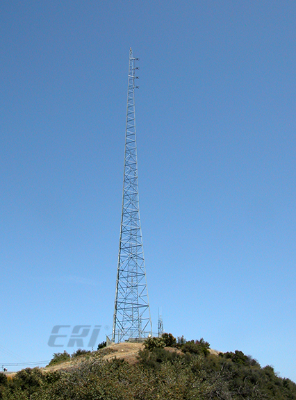
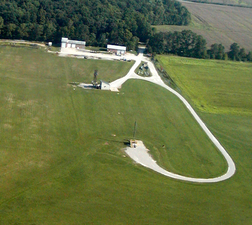
ERI’s Antenna Test Range has been in continuous use longer than any other Test Range used by any broadcast antenna supplier. This is important because long experience is needed to fully characterize a test facility so that it delivers accurate results. This process requires years and newly constructed antenna test facilities cannot be trusted to provide accurate and repeatable measurements.


The range includes two turntables and one static stand. The turntables are rated for deadweight loads of 12,000 and 25,000 pounds – respectively. In addition to the range measurement and test facilities, the site includes a machine shop and fabrication facility for constructing replica tower sections independent of ERI’s main factory. The test site is also equipped with a static stand workstation for the setup and tuning of Batwing television antennas and Master FM Antenna Systems. The ERI test range has its own dedicated staff of tower climbers, machinists, technicians, and engineers

Posted on

First module assembled for a new five station FM channel combiner

ERI’s Filter Lab technicians have begun assembly for system testing for a new five-station constant impedance FM channel combiner. The combiner will be fully assembled and tuned here at ERI’s factory and then disassembled for shipment and reassembly at the customer site. The individual combiner modules are configured in vertical stands to minimize the floor space they require. The system also includes a power divider at the combined output to divide the combined output into two transmission lines, which will feed the top and bottom halves of the 16-bay AXIOM® Master FM Antenna system.

Posted on

New Integrated UHF Channel Combiner

The product shown is a new Model UF3000-323-TCC UHF Tee Combiner built to combine RF Channel 14 and 36 into a broadband UHF panel antenna. It is a channel combiner only with two (2) three-section UHF bandpass filters in a single integrated case. The combiner is rated to handle up to 3 kW average power at each input, 6 kW at the combiner output. Insertion loss is only 0.1 dB. The combiner includes single port directional couplers at each of its 1-5/8-inch EIA flanged inputs and a single port adjustable directional coupler at the 3-1/8-inch EIA flanged combined output.

Posted on

A top-mounted elliptically polarized TRASAR® television antenna

The antenna pictured in East Tennessee PBS’s Sneedville, Tennessee, main facility WETP. The signal serves communities in northeast Tennessee, southeast Kentucky, and western North Carolina, and Virginia. This is an elliptically polarized antenna, and so the climbing facilities are a fiberglass ladder to minimize distortion of the vertically polarized azimuth pattern. The antenna is installed on a 540-foot guyed tower ERI manufactured and installed in 2005.

Posted on

Welding Leg Flanges to a New LAMBDA® Optimized FM Mounting System

Welding flanges onto the legs of a new ERI LAMBDA® Optimized FM Mounting System. The LAMBDA® mounting system was designed initially to reduce FM antenna failures due to stresses from tower movement.  The design specified a maximum bending radius of the top-mounted free-standing tower sections, and this resulted in a very stiff tower designed to support side-mounted FM antennas. Typical 20-foot tower sections do not allow symmetrical antenna element mounting locations because the cross members will have a different geometry behind each of the array elements. LAMBDA tower sections make the signal scattering from the tower a constant because the structural member spacing is a halfwave at the operating FM frequency.  All the antenna array elements see the same tower face geometry because the tower’s reflected (scattered) signal is identical for each bay of the array.